Control Technology
Description of the research group:
The control technology group deals with the modeling, observation and control of linear, unsafe dynamic systems. In practice, the uncertainty or the information deficit mostly results from incomplete modeling, from indirect measurements (observations), from highly error-prone or incomplete measurements or from the discretization for the use of digital computers.
The control loop are used in:
- mechatronic (e.g. assistance systems in vehicle technology),
- micro-optoelectronic (e.g. micro-optical analysis system),
- optomechatronic (e.g. image feedback control)
- and acoustic (e.g. "active noise control")
systems together.
When designing the controller, linear (e.g. H∞ modifications), linear adaptive (e.g. predictor / corrector method) or non-linear (e.g. Lyapunov method) concepts are developed and used experimentally. In connection with measurement uncertainties, fuzzy models and linear and non-linear observation models are examined. Experimental identification methods, such as frequency characteristic methods, play an important role in the case of large modeling deficits. In the case of image feedback control, problem areas from the multi-dimensional signal processing such as object and environment recognition also arise.
Contact Person


Automatic Control & Accustic
30823 Garbsen
Automatic Control & Accustic
Control Engineering
-
Macro-micro kinematics for micro-assemblyThe focus of the research project lies in exploring methods for developing a handling system, which will serve as the actuator basis for a clinically suitable, ultra-precise mechatronic assistance system. The goal is to achieve a resolution of 1 µm in a working volume of 10 mm³, where the working volume can be flexibly positioned in space. The technical implementation is achieved by coupling piezoactuator technology with a 6-axis precision robot (µKRoS316). The robot is responsible for positioning the tools throughout the entire working area (macro positioning). The micro positioning unit takes on tasks such as compensating for the robot's positioning inaccuracies, counteracting vibrations, and precisely moving the tool. The work program can be divided into five areas according to the above-mentioned focus areas: Design of a coupled control Construction of an external measurement system for real-time 6D positioning Research on methods to improve the 6D positioning accuracy of positioning units Matching of the coordinate systems of positioning units and the measurement system and path planning Development and construction of the toolsetYear: 2015
![]()
-
Control concepts for image processing-supported movement of an objectAt the Institute for Measurement and Control Engineering, an experimental setup for stabilizing a 3D inverted pendulum was built. To determine the position of the pendulum, it is necessary to determine the positions of the pivot point and the tip of the pendulum. The position of the tip of the pendulum – specifically, the white ball – is determined with the help of a high-speed camera. The CMOS camera takes 148 frames per second. The relationship between the 2D image coordinates and the 3D world coordinates is established through a prior camera calibration. The position of the pivot point or the cart is determined via the stepper motors. The aim of the control is to keep the pendulum in a stable upright position at one location; in the second step, the pendulum should move stably on a path – specifically, on a circle. A PID controller, a state feedback controller, an MRAC (model reference adaptive control) controller with full state feedback, and a nonlinear controller are used. Technically, the control is implemented with the help of the xPC Target Toolboxes from MATLAB. The control algorithms are executed by the Target PC. On the Host PC, only the image processing is carried out, and the results are sent to the Target PC via the Ethernet connection. These control concepts could be used for stabilizing patients in radiation therapy.Year: 2015
![]()
-
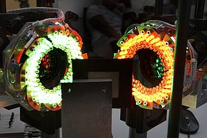
Image feedback control of an optomechanical derotator for measurements on rotating componentsRotating components are installed in a wide variety of machines. To ensure efficient and safe operation, checking these is essential. This can be most reliably achieved through measurements, especially if these are carried out non-contact and during actual operation. This way, it can be ensured that the results are not falsified by the measuring system.Led by: Dr. Ing. Christian PapeTeam:Year: 2017
![]()
-
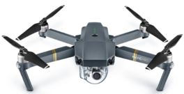
Simultaneous Localization and Mapping System using Aerial CameraIn the areas of robot navigation, localization and mapping, as well as augmented or virtual reality, the demand for real-time 3D reconstruction methods has increased significantly in recent years. A promising approach to implementing 3D reconstruction methods is the principle of Simultaneous Localization and Mapping, known as SLAM. The goal of this method is, on the one hand, the 3D reconstruction of the environment, and on the other hand, the relative localization and tracking of moving objects.Led by: Dr.-Ing. Christian PapeTeam:Year: 2018Duration: 01.01.2018 – 31.12.2020
![]()
-
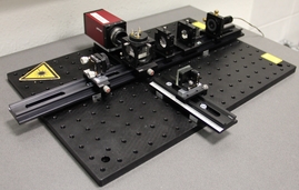
Robot-assisted assembly of optical systems using predictor-corrector methodsThis research project focuses on the functional construction of optical systems and aims to reduce the high required tolerances of both the optical components and the positioning systems. Furthermore, it also aims to ensure a lower rejection rate of optical components during the manufacturing process.Led by: Dr.-Ing Christian PapeTeam:Year: 2018
![]()