Multiscale Geometry Inspection of Joining Zones (SFB 1153 C5)
| Led by: | PD Dr.-Ing. Dipl.-Phys. Markus Kästner; Dr.-Ing. Lennart Hinz |
| E-Mail: | pascal.kern@imr.uni-hannover.de |
| Team: | Pascal Kern, M. Sc. |
| Year: | 2015 |
| Funding: | DFG |
| Duration: | 2015-2027 |
| Further information | https://www.imr.uni-hannover.de/en/forschung/forschungsprojekte/forschungsprojekte-detailansicht/projects/multiskalige-geometriepruefung-sfb-1153-c5 |
Collaborative Research Center 1153 - Process Chain for the Production of Hybrid High-Performance Components through Tailored Forming - C5 - Multiscale Geometry Inspection
The research focus of subproject C5 is the area-wide 3D geometry reconstruction of forging-heat Tailored Forming components using optical triangulation sensors. Inspecting the geometric features of the joining zone after each individual process step allows for the adjustment of the manufacturing process, early error detection, as well as the evaluation of component distortions, which can arise from inhomogeneous cooling processes of hybrid material pairings.
Video
MOTIVATION AND OBJECTIVES
Es werden unterschiedliche Sensorkonzepte unter Nutzung aktorbasierter und algorithmischer Kompensationsverfahren für den Lichtablenkungseffekt im wärmeinduzierten inhomogenen Brechungsindexfeld erforscht.


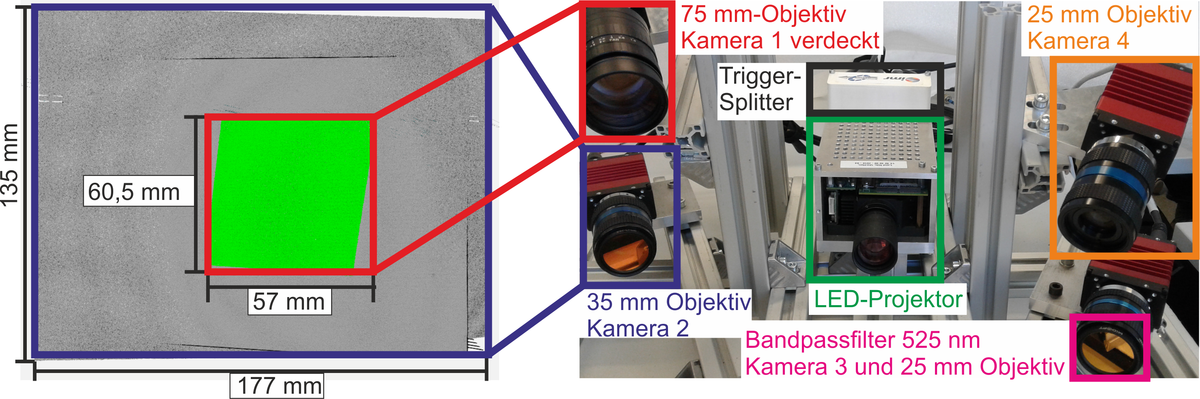
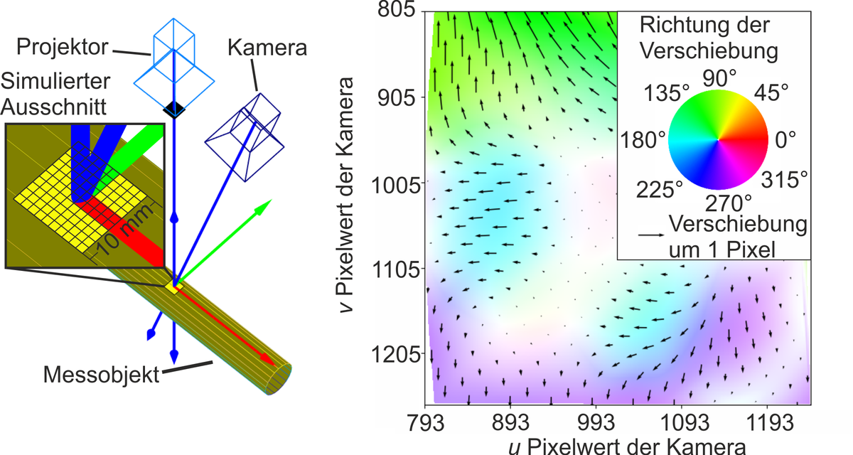
To achieve an algorithmically compensated geometry measurement, a multi-camera structured light projection sensor is being developed (Fig. 1). This allows for the redundant acquisition of geometric data from overlapping measurement areas based on different triangulation angles. Here, all camera-projector combinations form so-called stereo pair measuring units, with which 3D geometric data can be acquired. By analyzing the stereo pair measurement results, which are affected to varying degrees by the light deflection effect, and based on simulations of refractive index fields, an algorithmic correction of measurement values for cylindrical components can be realized. Additionally, using the Finite Element (FE) simulation software Comsol, a numerical model was implemented that illustrates the multiphysical relationship between heat-induced density reduction of air and the resulting light deflection effect, enabling virtual triangulation measurements under optical inhomogeneity (Fig. 2).


CURRENT WORK AND OUTLOOK
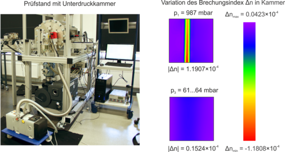
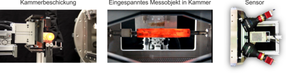
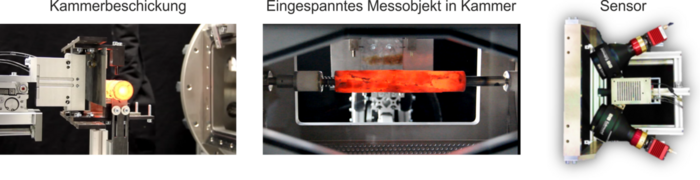
For the experimental validation of the algorithmic measurement correction and to carry out shrinkage or distortion measurements directly after the forming process, a measurement chamber sensor concept is being explored. This concept, through pressure reduction, aims to enable geometry characterization of hot Tailored Forming components with negligible refractive index field influence. The vacuum approach was initially validated using refractive index measurements by means of the two-dimensional (2D) background oriented schlieren (BOS) method. Fig. 3 shows the test setup with a vacuum chamber. The refractive index field around a hot measuring rod (approximately 1000 °C) inside the chamber at ambient pressure (p=987 mbar) and at reduced chamber pressure (about 64 mbar) is shown on the right side. It is evident that a reduction in pressure significantly decreases the variation of the refractive index in air. The loading of the vacuum chamber, a red-hot measuring cylinder within the chamber, and the sensor head for carrying out geometry measurements through the chamber measuring window are shown in Fig. 4.


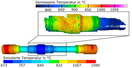
For a comprehensive characterization of forging processes, it is also planned to couple a thermography camera with a triangulation sensor. This will enable the correlation of experimentally determined temperature and geometry data (4D model of the measurement object, Fig. 5). By comparing forming simulations and measurement data, a validation of the simulations can be achieved.


